- Full scale flow ranges from 1 to 150 GPM and 10 SCFM to 1,300 SCFM

- Connection sizes from 1/4-inch to 8-inch NPT, BSP, SAE or flange
- Construction materials: Brass, Stainless Steel, or Aluminum
- Spring loaded, mechanical design mounts in any orientation
- Viscosity compensating for liquids to 500 SSU
- Pressure ratings to 6000 PSIG
- Optional high temperature design up to 600 degrees F (315 C)
- Optional field adjustable switches
- Optional 4-20mA transmitter
* FACTORY PRE-CALIBRATED TO CUSTOMERS SPECIFICATION
FLOW RATE MONITORS
INDICATORS, SWITCHES, TRANSMITTERS AND FOR WATER, OILS, PAINTS, AIR, AND GASES
SERIES HFR, HFS, HFDS, AND HFT
FEATURES/BENEFITS:
- Direct Reading Flow Rate Indication
- Optional Switch(es)
- Optional (field selectable) transmitter outputs of:
4-20mA, 0 to 5 VDC, or 1 to 5VDC, square wave pulse - Pressures up to 6000 PSIG (413 Bar)
- Maximum Temperatures to 600°F (315°C)
- Not effected by viscosity changes up to 500 SSU/100 Centipoise
- Versatile mounts in any orientation
- No Straight Pipe Runs Required
- Easy to read with Dark or Opaque Fluids
- Flow Ranges:
Liquids: 0.5 to 175 GPM
Air & Gases: 2 to 1300 SCFM - Connections Sizes Available:
1⁄4 through 2 Inch NPT, SAE, BSP, and Flanges
GENERAL DESCRIPTION:
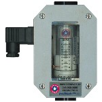
Sure Flow Products variable area flow rate indicators are designed for tough industrial applications. This flow indicator is mechanical with a spring-loaded float and magnetic follower. This allows for mounting in any orientation and is ideal for use with dark or opaque fluids. The sharp edge orifice provides excellent measurement stability. These unique flow devices are not affected by changes in viscosities up to 500 SSU. For viscosities greater than 500 SSU and for air or gas applications, each flow indicator is individually calibrated for customer operating conditions.

| SERIES HFS* : High Pressure/Temperature Indicators, Switches, and Transmitters | |
|---|---|
| Measuring Accuracy: | ±2.5% of full scale on center 1/3 or measuring range ±1% or full scale over the entire scale range |
| Repeatable: | ±1% or full scale |
| Flow Measuring Range: | 0.05-150 GPM |
| Max. Operating Pressure: | Aluminum or brass monitor: 3500 PSIG (240 Bar) Stainless steel monitor: 6000 PSIG (410 Bar) |
| MAX. Operating Temp: | Media: 240°F (110°C) Ambient: 180°F (82°C) |
| Max. Pressure Drop: | Consult Sure Flow Products |
| Standard Calibration: | Oil monitors: DTE 25° @ 110°F (43°C), 0.873 sgWater monitors: Tap water @ 70°F (21°C). 1.0 sg |
| Enclosure: | NEMA type 4X (UL approved) |
| Alarm Switch: | 4% of full scale |
| Alarm Switch Contact: | SPDF (dry contact): UL/CSA rating at 10 amps and 1/4 hp, 125 or 250 VAC, 1/2 amp, 125 VDOC, 1/4 amp, 250 VDC (3 amps, 125 VAC lamp load |
| Power Requirement: | 12-35 VDC |
| Load Driving Capacity: | 4-20: Load resistance is dependent on power supply voltage. Use the following equation to calculate the maximum load resistance: Max. loop load (Ω)=50 (power supply volts-12). 0-5 VDC: Minimum load resistance 1000~. 1-5 VDC: Minimum load resistance 25K~. Square wave pulse: Min. load resistance I000~. |
| Over-Current Protection: | Self-limiting at 35mA |
| Resolution: | 10 bit (0.1%) |
| Isolation: | Inherently isolated from the process |
| Response Time: | < 100 milliseconds |
MATERIALS OF CONSTRUCTION
| WETTED COMPONENTS | |||
|---|---|---|---|
| CASING END PORTS TAPERED SHAFT | Aluminum | Brass | Stainless Steel |
| SEALS | Bauna-N (Std), EPR, Viton®, Kalrez® | Viton® w/Teflon® (Std), Buna-N, EPR, Kalrez® | |
| TRANSFER MAGNET | Teflon® Coated Alnico | ||
| FLOATING ORIFICE DISK | Stainless Steel | ||
| ALL OTHER INTERNAL PARTS | Stainless Steel | ||
| NON-WETTED COMPONENTS | |||
| ENCLOSURE & COVER | Aluminum | ||
| SEALS | Buna-N | ||
| WINDOW | Pyrex | ||
| DIN CONNECTOR | Polymide | ||
DIMENSIONS SERIES HFR

| Dimension in Inches | SIZE 2 | SIZE 3 | SIZE 4 | SIZE 5 | |
|---|---|---|---|---|---|
| Diameter | 1-1/4 | 1-7/8 | 2-3/8 | 3-1/2 | |
| Length | 4-13/16 | 6-9/16 | 7-5/32 | 10-1/8 | 12-5/8 |
| Port Size NPTF: | 1/8, 1/4 | 1/4, 3/8, 1/2 | 3/4, 1 | 1-1/4, 1-1/2 | 2 |
| SAE#: | 6, 8, 10 | 12, 16 | 20, 24 | 32 | |
| BSP: | 3/8, 1/2 | 3/4, 1 | 1-1/4, 1-1/2 | 2 | |
DIMENSIONS SERIES HFS, HFDS, HFT

| Dimension in Inches | SIZE 3 | SIZE 4 | SIZE 5 | |
|---|---|---|---|---|
| Length | 6-9/16 | 7-5/32 | 10-1/8 | 12-5/8 |
| Width | 2-3/16 | 2-15/16 | 3-13/16 | |
| A | 4 | 4-1/2 | 5-5/16 | |
| B | 1-7/8 | 1-7/8 | 1-7/8 | |
| C | 4-7/8 | 5 | 6-3/4 | |
| D | 2-1/4 | 2-7/8 | 3-1/4 | |
| Port Size NPTF: | 1/4, 3/8, 1/2 | 3/4, 1 | 1-1/4, 1-1/2 | 2 |
| SAE#: | 6, 8, 10 | 12, 16 | 20, 24 | 32 |
| BSP: | 3/8, 12 | 3/4, 1 | 1-1/4, 1-1/2 | 2 |
MODEL SELECTION:
Example: HFS /4 – 20GPM -.750- B – 2
SERIES:
- HFR = Flow Rate Indicator
- HFS = Flow Rate Indicator w/Switch
- HFDS = Flow Rate Indicator w/2 Switches
- HFT = Flow Transmitter
SIZES AVAILABLE FLOW RANGES:
| SIZE | GPM | RANGES | ||
|---|---|---|---|---|
| LIQUID GPM |
AIR & GAS SCFM |
|||
| /2 or /3 | 1 | = | .1 to 1 or .05 to 1 |
1.5 to 12 |
| /3 | 2 | = | .2 to 2 | 4 to 23 |
| /4 | 5 | = | .5 to 5 | 6 to 60 |
| /4 | 10 | = | 1 to 10 | 10 to 100 |
| /4 | 10 | = | 1 to 10 | 10 to 100 |
| /4 | 15 | = | 1 to 15 | 15 to 150 |
| /4 | 20 | = | 2 to 20 | 20 to 215 |
| /5 | 25 | = | 2 to 25 | 20 to 250 |
| /5 | 30 | = | 3 to 30 | 30 to 330 |
| /5 | 40 | = | 4 to 40 | 30 to 400 |
| /5 | 50 | = | 5 to 50 | 30 to 470 |
| /5 | 75 | = | 8 to 75 | 30 to 750 |
| /5 | 100 | = | 10 to 100 | 150 to 900 |
| /5 | 150 | = | 50 to 150 | 150 to 1300 |
Other units of measure available, consult Sure Flow
CONNECTIONS SIZES/TYPES:
| .250 = 1/4 inch NPT .250BSP = 1/4 inch BSP |
6 SAE = #6 SAE |
| .375 = 3/8 inch NPT .375BSP = 3/8 inch BSP |
8 SAE = #8 SAE |
| .500 = 1/2 inch NPT .500BSP = 1/2 inch BSP |
10 SAE = #10 SAE |
| .750 = 3/4 inch NPT .750BSP = 3/4 inch BSP |
10 SAE = #10 SAE |
| 1.00 = 1 inch NPT 1.00BSP = 1 inch BSP |
10 SAE = #12 SAE |
| 1.25 = 1-1/4 inch NPT 1.25BSP = 1-1/4 inch BSP |
10 SAE = #16 SAE |
| 1.5 = 1-1/2 inch NPT 1.5BSP = 1-1/2 inch BSP |
10 SAE = #20 SAE |
| 2.00 = 2 inch NPT 2.00BSP = 2 inch BSP |
10 SAE = #24 SAE |
For flanged connections, consult Sure Flow
BODY MATERIAL:
- A = Aluminum
- B = Brass
- SS = Stainless Steel
SEAL MATERIALS:
- 1 = Viton
- 2 = Buna N
- 3 = Ethylene Propylene
- 4 = Teflon & Kalrez
OPTIONAL MOUNTING ORIENTATION/SPECIAL CALIBRATION:
- R= Horizontal Mount – left to right flow
- L= Horizontal Mount – right to left
- D= Vertical Mount – flow down
- B= Bidirectional
Note – Standard is vertical mount – flow up. However, meter can be mounted in any orientation. Options above include turning of the calibrated number for ease in reading.
High Temperature Option
(rate indicators only, consult Sure Flow Products)
- HT = 400°F (requires Viton/Teflon seal)
- HT6 = 600°F (requires Teflon/Kalrez seal)
S* – Calibrated for a viscosity greater than 500 SSU, or Specific Gravity greater than 1.0 (please specify both viscosity and specific gravity. Ex: S1000/.9 means calibrate for 1000 SSU and S.G. of .9
